Half-Wave Voltage Doubler (no transformer)
Voltage doublers produce twice the DC voltage of a standard rectifier. There are two types of voltage doubler: half-wave voltage doubler and full-wave voltage doubler. In both cases, the ripple voltage frequency is the same as the input voltage frequency.
In full-wave rectification using traditional rectifiers, the ripple voltage frequency is twice the input voltage frequency. In this process, the ripple voltage frequency is twice that of the input voltage frequency.
The advantage of the half-wave voltage doubler is that it has a line that is common to the input and output (see diagram). This line can be used as a common or ground connection and can be connected to the chassis or metal base of the connected equipment.
The ground or common terminal must be clearly labeled to avoid an inverted connection, which could have unpleasant consequences. Otherwise, the chassis or metal base of the equipment would be connected to the “+” terminal.
Operation of a Half-Wave Voltage Doubler
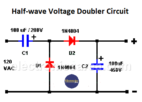
Half-Wave Voltage Doubler
During the first negative half-cycle of the input waveform, diode D1 becomes directly polarized, allowing current to pass through capacitor C1. The capacitor charges to the peak value of the input voltage. If the peak value is V_(max), then the capacitor is charged to this voltage. During this cycle, diode D2 is inversely polarized and does not conduct.
During the next half-cycle (the positive half-cycle) of the input voltage, the D1 diode is reverse polarized and does not conduct. The D2 diode is directly polarized, allowing current to flow through the capacitor C1, diode D2, and capacitor C2.
At the start of the negative half-cycle, the capacitor C2 is discharged, while C1 is charged at Vmax, which is the peak value of the input voltage. Then, C2 is charged at twice the input peak voltage. The current peak input voltage and the accumulated voltage at capacitor C1 are added together.
Important: It has been assumed that the input voltage is 120 VAC. For a design using 220/240 VAC, replace the capacitors with higher-voltage ones.
You may be interested in: Half-Wave Rectifier Circuit Diagram Using a Transformer


