Instruments and Measurements
Home /
Instruments and Measurements
Measuring Low Resistances
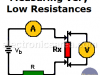
There are cases where the resistance is too low and a direct use of the ohmmeter is not practical. So a special method is needed
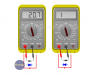
Multimeter – VOM – Tester
This tool is known as a VOM, although there are multimeters that can measure many other quantities.
Measure Resistance with an Analog Multimeter
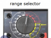
How to use the analog multimeter / VOM to measure resistance (ohms). How to use the range selector and how to set the needle to zero ohms.
Resistance measurement of delicate components
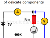
There is a special way of resistance measurement when the component to be measured is very sensitive or delicate.
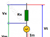
What is the Wheatstone Bridge Circuit?
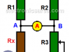
This circuit was designed in 1833 by Samuel Hunter Christie (1784-1865). However, It was Mr. Charles Wheatstone who gave many uses to the Wheatstone bridge circuit when he discovered it in 1843.
How to Extend the Voltage Range of an Analog Multimeter?
How to extend the voltage range of an analog Multimeter? In order to extend the voltage range, a resistor is placed in series with the multimeter. Calculation example.
How to test Diodes and How to test Transistors using Multimeter?
Method to follow to test a diode or transistor to know if it is working properly
What is a Logic Probe?
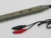
A logic probe is a simple and inexpensive instrument contained within a pen-like tube. It has 3 LED indicators that show the status of the point under test. 5 DIY Logic Probes
kWh – Cost of Electric Energy
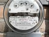
The unit of measurement used in the electricity bill is the kWh, however in the electrical or electronic products that we buy in stores, the unit of electricity consumption is given in watts or kilowatts.
Scientific Notation – Engineering Notation
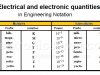
Scientific notation and engineering notation allow the representation of very large or very small quantities, very common in engineering and technical fields