Home / Power Supplies /
Transformerless Power Supply Circuit
We will use a Zener diode, among other elements, to create the transformerless power supply circuit. This means that our power supply will provide a limited range of current values, meaning there will be a maximum and minimum current that the power supply can deliver.
The power supply must be connected to the entire circuit. If you want to disconnect the circuit, you must disconnect the entire unit.
How does the transformerless power supply circuit work?
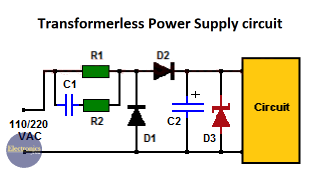
- A Zener diode (D3) maintains a constant voltage on the load.
- Two semiconductor diodes (D1 and D2) form a half-wave rectifier.
- A filter capacitor (C2) smooths the signal coming from the rectifier diodes before applying it to the Zener diode cathode.
- The R2 resistor and C1 capacitor reduce the input voltage (110 or 220 volts AC at 50 or 60 Hz) to a level suitable for the Zener diode.
There is a voltage drop on both R2 and C1. The voltage drop on C1 is due to capacitive reactance (Xc), which depends on the capacitor value and the frequency of the applied signal (50 or 60 Hz). Although the original design was made for a 220-volt, 50 hertz input signal, it was tested with a 110-volt, 60 hertz input signal and ran smoothly.
Xc = 1/(2.π.f.C), where:
- Xc = capacitive reactance (in ohms)
- π = 3.14159265359
- f = 50 or 60 (Hertz)
- C = capacitor value (farads).
Resistor R1 assists in unloading capacitor C1 when the circuit is disconnected. This circuit can deliver a maximum of 100 or 120 milliamps.
Caution! The circuit is directly connected to the main voltage (110/220 VAC), so extra care must be taken when conducting tests.
List of components for transformerless power supply circuit:
- 1 4.7 to 5.6 volts Zener diode (D3).
- 2 400-volt/5-amp common rectifier diodes (D1 and D2).
- 1 100K to 120K (kilohms) resistor (R1).
- 1 33 ohms resistor (R2).
- 1 2.2 µF/300 V or greater capacitor (C1).
- 1 220-1000 μF (microfarads) electrolytic capacitor (C2).


Hi can you suggest a circuit from 220 volts ac to 120 volts ac at 60hz. To power a 110volts AC 10 watts light bulb.
Thank you very much in advance.
Hello
I’m not sure I understand the question.
I think it is only necessary to use a 220 to 110VAC transformer, between 220VAC and the 10 watts bulb,
If that’s not what you want to know, please clarify the question.
Regards