Home / Circuits / Battery related /
12 Volt Car Battery Charger with LM7815
This 12 volt car battery charger is a circuit with few components that allows us to charge a common car battery. Battery charging stops when it reaches its maximum voltage.
The circuit charges the battery of our car at maximum current and decreases as the battery voltage reaches its maximum, when the charging current will be zero. At that time, the battery will be at its maximum voltage.
12 Volt Car Battery Charger Circuit Operation
The set of 3 diodes in series, all of them in parallel with the series arrangement of resistor R1 and the emitter base junction of transistor Q1, create a constant current source. Resistor R1 sets the current flowing through the transistor. Analyze the diagram.
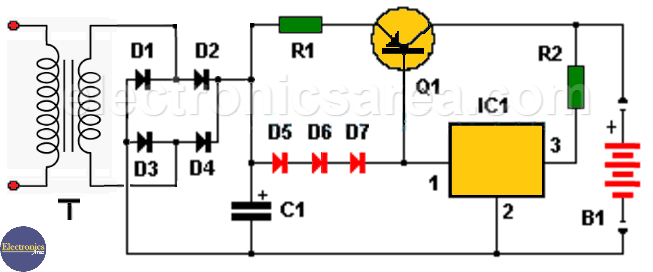
12 Volt Car Battery Charger with LM7815
Each diode has a voltage drop of 0.7 volts (same as the base-emitter junction of the transistor). The approximate current through R1 is: I = V / R. I = 1.4 volts /0.33 ohms = 4.2 amps.
The function of the voltage regulator is to keep the current source active. When the battery is fully charged (the voltage is approximately 15 volts) almost no current flows through the IC1 regulator and the Q1 transistor goes into cut-off because no current passes through its base.
Resistor R2 is used to limit current at the output and through regulator IC1. Resistor R2 allows current to pass through IC1, so that Q1 has current at its base and is saturated until the output voltage reaches approximately 13.5 volts.
When the voltage reaches 13.5 volts, the current begins to decrease and will continue to decrease as the voltage continues to rise. Lowering the value of R2 will increase the final battery charge voltage.
If you want the battery to charge at a lower voltage, you can place one or more diodes in series on one of its terminals, in the direction of current flow. This will cause a drop of approximately 0.7 volts per diode.
Circuit component list
- R1 = 0.33 ohm resistor, 10 watts
- R2 = 8.2 ohm resistor, 2 watts
- C1 = 10,000uF / 100V electrolytic capacitor
- D1 = D2 = D3 = D4 = D5 = D6 = D7 = SB560 (5 amps)
- Q1 = PNP MJ15004 or NTE88 transistor
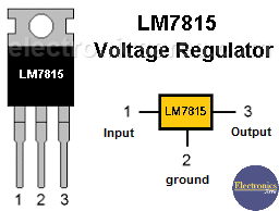
- IC1 = voltage regulator 7815.
- B1 = 12 volt car battery.
- T = Transformer 120 / 240VAC to 18VAC, 3 amps on the secondary.