Electronics Area

Electrical and Electronics Tutorials and Circuits
  • Home
  • Tutorials
    • DC Theory Tutorials
    • Alternating Current (AC)
    • Digital Electronics
  • Semiconductors
  • Circuit diagrams
    • Audio Circuits & Projects
    • Control Circuits
    • Detector Circuits and Projects
    • Power supply
    • Timer Circuits and Projects – 555 Timer
    • Op. Amp. Circuits
    • LED Circuits & Projects
    • Alarm Circuits and Projects
    • Test circuits
    • Battery chargers. Battery monitors and Projects
  • Instruments and Measurements
Temperature alarm circuit with Op. Amp.

Temperature alarm circuit with Op. Amp.

  •  
  •  
  •  
  •  
  •  
  •  
  •  January 13, 2020
  •  Temperature alarm circuit with Op. Amp.
  •  Posted by Marcel at 3:28 pm
  •  No Responses
  •  Alarm Circuits
  •  Tagged with: temperature

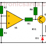
Temperature alarm circuit with 741 operational amplifier

This temperature alarm circuit with operational amplifier activates a relay when the temperature of the place to be controlled exceeds a set level. Useful for an oven temperature control or a cooling system

Full Story
Over temperature alarm circuit using Thermostat

Over temperature alarm circuit using Thermostat

  •  
  •  
  •  
  •  
  •  
  •  
  •  January 7, 2020
  •  Over temperature alarm circuit using Thermostat
  •  Posted by Marcel at 2:18 pm
  •  No Responses
  •  Alarm Circuits
  •  Tagged with: temperature, thermostat

Over temperature alarm circuit using Thermostat

This alarm circuit uses the 67L080 thermostat (TH) and can be assembled easily, due to the small number of components required.

Full Story
Temperature to Voltage Converter using Thermistor (PCB)

Temperature to Voltage Converter using Thermistor (PCB)

  •  
  •  
  •  
  •  
  •  
  •  
  •  September 11, 2018
  •  Temperature to Voltage Converter using Thermistor (PCB)
  •  Posted by Marcel at 8:35 pm
  •  No Responses
  •  Detector Circuits
  •  Tagged with: PCB, temperature

This circuit convert the sensed temperature by a thermistor into a voltage level. The circuit achieves an acceptable performance between 0°C and 24°C

Full Story

Most Popular

  • Audio Splitter Circuit Diagram - 1 Input - 4 Outputs
    Audio Splitter Circuit Diagram – 1 Input – 4 Outputs
  • OR and AND logic gates made with diodes
    OR and AND logic gates made with diodes
  • ON-OFF Switch circuit using a 555 timer (PCB)
    ON-OFF Switch circuit using a 555 timer (PCB)
  • Humidity sensor circuit using the 555 timer
    Humidity sensor circuit using the 555 timer

Follow Me

Twitter Facebook

Recent Posts

  • How do I test a Zener diode? – A simple method
  • Equivalent transformer circuits (power, audio, video and RF)
  • Wirewound Resistor
  • Light detector circuit using LDR (automatic night light)
  • The Decibel – Voltage Gain & Power Gain
  • Blown Fuse Indicator Circuit using one transistor
  • Logic Probe using NOT Gates
  • Resistors in Series – The Equivalent Resistance
  • How to increase the output voltage of 78XX regulators?
  • Mesh Current Method – Steps to follow – Example

Privacy
© 2015 Electronics AreaSuffusion theme by Sayontan Sinha