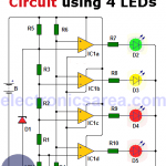
This simple car battery monitor allows us to know the voltage of the battery at all times. To achieve this, 4 LEDs are placed somewhere on the dash of the car. Each LED has a label indicating the battery voltage at that time.
This simple car battery monitor allows us to know the voltage of the battery at all times. To achieve this, 4 LEDs are placed somewhere on the dash of the car. Each LED has a label indicating the battery voltage at that time.
This car battery monitor circuit is very simple and very interesting. How many times have you found that the car does not start because the battery is discharged?
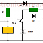
Car Battery Booster Circuit
This Car Battery Booster Circuit, is very useful when the car battery has low charge or does not deliver the expected current to operate the starter motor.