Electronics Area

Electrical and Electronics Tutorials and Circuits
  • Home
  • Tutorials
    • DC Theory Tutorials
    • Alternating Current (AC)
    • Digital Electronics
  • Semiconductors
  • Circuit diagrams
    • Audio Circuits & Projects
    • Control Circuits
    • Detector Circuits and Projects
    • Power supply
    • Timer Circuits and Projects – 555 Timer
    • Op. Amp. Circuits
    • LED Circuits & Projects
    • Alarm Circuits and Projects
    • Test circuits
    • Battery chargers. Battery monitors and Projects
  • Instruments and Measurements
Lie Detector Circuit Using Two Transistors

Lie Detector Circuit Using Two Transistors

  •  
  •  
  •  
  •  
  •  
  •  May 7, 2019
  •  Lie Detector Circuit Using Two Transistors
  •  Posted by Marcel at 4:41 am
  •  No Responses
  •  Detector Circuits

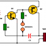
This simple lie detector consists of two transistors and other additional components and can detect if a person does not tell the truth (the person is lying), using two sensors placed directly on the skin.

Full Story
Temperature to Voltage Converter using Thermistor (PCB)

Temperature to Voltage Converter using Thermistor (PCB)

  •  
  •  
  •  
  •  
  •  
  •  
  •  September 11, 2018
  •  Temperature to Voltage Converter using Thermistor (PCB)
  •  Posted by Marcel at 8:35 pm
  •  No Responses
  •  Detector Circuits
  •  Tagged with: PCB, temperature

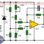
This circuit convert the sensed temperature by a thermistor into a voltage level. The circuit achieves an acceptable performance between 0°C and 24°C

Full Story
Humidity sensor circuit using the 555 timer

Humidity sensor circuit using the 555 timer

  •  
  •  
  •  
  •  
  •  
  •  
  •  September 6, 2018
  •  Humidity sensor circuit using the 555 timer
  •  Posted by Marcel at 11:44 am
  •  2 Responses
  •  Detector Circuits
  •  Tagged with: sensor

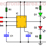
This simple humidity sensor circuit, shows us the humidity level that a ground under test has. To achieve the goal, a couple of probes are used.

Full Story
Temperature Gauge Circuit Using LM324 (PCB)

Temperature Gauge Circuit Using LM324 (PCB)

  •  
  •  
  •  
  •  
  •  
  •  April 16, 2018
  •  Temperature Gauge Circuit Using LM324 (PCB)
  •  Posted by Marcel at 12:08 pm
  •  No Responses
  •  Detector Circuits

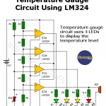
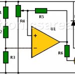
The temperature gauge circuit is implemented using four comparators. We use the LM324 integrated circuit, which has four 741 operational amplifiers (op amps) in a single package.

Full Story
 Newer Entries

Most Popular

  • Audio Splitter Circuit Diagram - 1 Input - 4 Outputs
    Audio Splitter Circuit Diagram – 1 Input – 4 Outputs
  • OR and AND logic gates made with diodes
    OR and AND logic gates made with diodes
  • ON-OFF Switch circuit using a 555 timer (PCB)
    ON-OFF Switch circuit using a 555 timer (PCB)
  • Humidity sensor circuit using the 555 timer
    Humidity sensor circuit using the 555 timer

Follow Me

Twitter Facebook

Recent Posts

  • How do I test a Zener diode? – A simple method
  • Equivalent transformer circuits (power, audio, video and RF)
  • Wirewound Resistor
  • Light detector circuit using LDR (automatic night light)
  • The Decibel – Voltage Gain & Power Gain
  • Blown Fuse Indicator Circuit using one transistor
  • Logic Probe using NOT Gates
  • Resistors in Series – The Equivalent Resistance
  • How to increase the output voltage of 78XX regulators?
  • Mesh Current Method – Steps to follow – Example

Privacy
© 2015 Electronics AreaSuffusion theme by Sayontan Sinha