Power Factor Definition
Power factor (PF) is the ratio of the energy converted into work to the electrical energy consumed by a circuit or device. In other words, PF is the ratio of the total voltage applied to a circuit to the voltage in the resistive circuit portion. PF is also:
- The cosine of the angle (cos(φ)) between the real power vector and the apparent power vector = Real Power/Apparent Power = Watts/Volts Amperes (W/VA)
- The cosine of the angle (cos(φ)) between the impedance vector and the resistance vector.
The AC power consumed by a circuit containing resistive (resistors) and reactive (capacitors and/or inductors) elements can be obtained using the following formulas: P = I x V x PF or P = IRMS VRMS x PF
Notes:
- RMS stands for root mean square.
- PF stands for power factor.
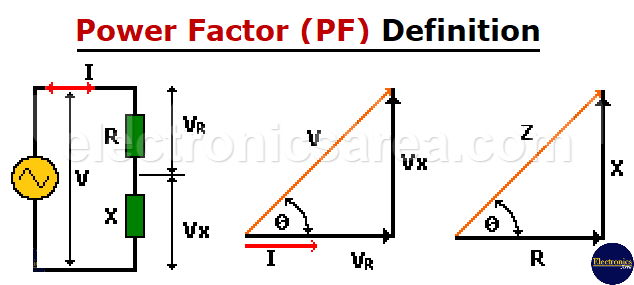
Refer to the circuit diagram above and its corresponding phasor diagram. Although the diagram shows an inductive value, this procedure is generally valid.
In the resistor R, the current (I) and voltage (VR) are in phase. The power dissipated in an impedance Z = (R + jX) is due only to resistance. Then: P = I x VR.
From the phasor diagram: VR = V cos(0).
By combining the last two formulas, we get: P = I x Vcos(0)
By comparing this equation with the expression: P = I x V x power factor, we can conclude the following: Power factor equals cos(0). This means that 0 is the phase angle of the impedance, or the angle between the voltage and current in the circuit.
Then PF = Cos(0) = VR/V = R/|Z|
Where: |Z| means the absolute value of Z The Z value is always positive, regardless of the sign.
The angle value will always fall within the following range:
- 0°: V and I are in phase (fully resistive circuit). Cos(0) = 1; therefore, PF = 1.
- 90: This occurs when V and I are 90° out of phase, which is a fully reactive circuit. Cos(0) = 0, PF = 0.
We aim for the highest possible power factor, where cos(0) approaches “1” (the most resistive possible).
How can the power factor be corrected?
Power factor (PF) correction is the process of compensating for a lagging current by creating a leading current. This is done by connecting capacitors in parallel with the power supply.
With enough capacitance connected to the power source, the power factor can be adjusted to be as close to unity as possible, reducing losses and electricity bills. A company’s typical power factor can reach 0.92 or slightly more.
For electric motors, which have coils that cause an inductive current to flow through them, the power factor (PF) can be corrected by placing capacitors in parallel with the motor’s starter. However, a disadvantage can arise when the motor’s load varies; overcorrection of PF or the opposite can result.
You may also like: Power in AC Circuit


