Electronics Area

Electrical and Electronics Tutorials and Circuits
  • Home
  • Tutorials
    • DC Theory Tutorials
    • Alternating Current (AC)
    • Digital Electronics
  • Semiconductors
  • Circuit diagrams
    • Audio Circuits & Projects
    • Control Circuits
    • Detector Circuits and Projects
    • Power supply
    • Timer Circuits and Projects – 555 Timer
    • Op. Amp. Circuits
    • LED Circuits & Projects
    • Alarm Circuits and Projects
    • Test circuits
    • Battery chargers. Battery monitors and Projects
  • Instruments and Measurements
How to use op amps with a single rail power supply?

How to use op amps with a single rail power supply?

  •  
  •  
  •  
  •  
  •  
  •  
  •  April 24, 2019
  •  How to use op amps with a single rail power supply?
  •  Posted by Marcel at 12:14 pm
  •  No Responses
  •  Operat Ampl
  •  Tagged with: op amp

How to use op amps with a single rail power supply?
Method #1: Voltage divider using two resistors. Method #2: Voltage divider using two Zener diodes.

Full Story
Wien-bridge Oscillator with Op Amp

Wien-bridge Oscillator with Op Amp

  •  
  •  
  •  
  •  
  •  
  •  
  •  September 18, 2014
  •  Wien-bridge Oscillator with Op Amp
  •  Posted by Marcel at 5:26 pm
  •  No Responses
  •  Alternating Current (AC)
  •  Tagged with: op amp, oscillator, signal generator

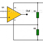
The Wien-bridge oscillator, consists of an Operational Amplifier (OA) in a non-inverting configuration with gain 1+R2/R1 and a RC feedback network

Full Story
Nonlinear Amplitude Control of a Sinusoidal Oscillator

Nonlinear Amplitude Control of a Sinusoidal Oscillator

  •  
  •  
  •  
  •  
  •  
  •  
  •  September 17, 2014
  •  Nonlinear Amplitude Control of a Sinusoidal Oscillator
  •  Posted by Marcel at 9:00 pm
  •  No Responses
  •  Alternating Current (AC)
  •  Tagged with: op amp, signal generator

Control of a sinusoidal oscillator is done in 2 phases: a linear method based in the frequency domain and a non-linear method using non linear mechanisms

Full Story

Follow us on Pinterest

Most Popular

  • Audio Splitter Circuit Diagram - 1 Input - 4 Outputs
    Audio Splitter Circuit Diagram – 1 Input – 4 Outputs
  • OR and AND logic gates made with diodes
    OR and AND logic gates made with diodes
  • ON-OFF Switch circuit using a 555 timer (PCB)
    ON-OFF Switch circuit using a 555 timer (PCB)
  • Humidity sensor circuit using the 555 timer
    Humidity sensor circuit using the 555 timer

Recent Posts

  • PWM – What is Pulse Width Modulation?
  • High-Speed Electronic Fuse for Solid-state Circuits
  • LM317T Current-limited 6V Battery Charger
  • How do I test a Zener diode? – A simple method
  • Equivalent transformer circuits (power, audio, video and RF)
  • Wirewound Resistor
  • Light detector circuit using LDR (automatic night light)
  • The Decibel – Voltage Gain & Power Gain
  • Blown Fuse Indicator Circuit using one transistor
  • Logic Probe using NOT Gates

Privacy
© 2015 Electronics AreaSuffusion theme by Sayontan Sinha