Electronics Area

Electrical and Electronics Tutorials and Circuits
  • Home
  • Tutorials
    • DC Theory Tutorials
    • Alternating Current (AC)
    • Digital Electronics
  • Semiconductors
  • Circuit diagrams
    • Audio Circuits & Projects
    • Control Circuits
    • Detector Circuits and Projects
    • Power supply
    • Timer Circuits and Projects – 555 Timer
    • Op. Amp. Circuits
    • LED Circuits & Projects
    • Alarm Circuits and Projects
    • Test circuits
    • Battery chargers. Battery monitors and Projects
  • Instruments and Measurements
Humidity sensor circuit using the 555 timer

Humidity sensor circuit using the 555 timer

  •  
  •  
  •  
  •  
  •  
  •  
  •  September 6, 2018
  •  Humidity sensor circuit using the 555 timer
  •  Posted by Marcel at 11:44 am
  •  2 Responses
  •  Detector Circuits
  •  Tagged with: sensor

This simple humidity sensor circuit, shows us the humidity level that a ground under test has. To achieve the goal, a couple of probes are used.
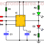
Full Story

Most Popular

  • Audio Splitter Circuit Diagram - 1 Input - 4 Outputs
    Audio Splitter Circuit Diagram – 1 Input – 4 Outputs
  • OR and AND logic gates made with diodes
    OR and AND logic gates made with diodes
  • ON-OFF Switch circuit using a 555 timer (PCB)
    ON-OFF Switch circuit using a 555 timer (PCB)
  • Humidity sensor circuit using the 555 timer
    Humidity sensor circuit using the 555 timer

Follow Me

Twitter Facebook

Recent Posts

  • LM317T Current-limited 6V Battery Charger
  • How do I test a Zener diode? – A simple method
  • Equivalent transformer circuits (power, audio, video and RF)
  • Wirewound Resistor
  • Light detector circuit using LDR (automatic night light)
  • The Decibel – Voltage Gain & Power Gain
  • Blown Fuse Indicator Circuit using one transistor
  • Logic Probe using NOT Gates
  • Resistors in Series – The Equivalent Resistance
  • How to increase the output voltage of 78XX regulators?

Privacy
© 2015 Electronics AreaSuffusion theme by Sayontan Sinha