Temperature Gauge Circuit Using LM324 IC
This temperature gauge circuit uses 4 LEDs to display the temperature level.
- The green LED indicates that the temperature is within the desired range.
- Two yellow LEDs indicate that the temperature is higher than normal, but not dangerous.
- The red LED indicates that the temperature is very high, and we need to take action.
To complement the visual high temperature warning, a buzzer is built into the circuit. The buzzer will sound in case of an emergency.
How does the temperature gauge circuit work?
The temperature gauge circuit is implemented using four comparators. We use the LM324 integrated circuit, which has four 741 operational amplifiers (op amps) in a single package.
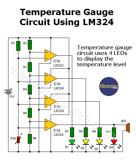
The schematic of the temperature gauge shows a voltage divider network with resistors R2, R3, R4, R5, and R6. The voltages obtained are 2.4V, 4.8V, 7.2V, 9.6V. Each of these voltages is connected directly to the non-inverting pin (+) of the op amps used as comparators.
The top terminal of the thermistor (R10) is connected directly to all the inverting (-) pins of the op amps. When the temperature changes, the voltage at the top of the thermistor changes.

The thermistor top terminal voltage is compared to the non-inverting terminal voltage on each comparator. If this is less than the voltage obtained by the voltage divider, the output of the corresponding comparator will light the LED.
The higher the temperature, the lower the thermistor voltage and the more LEDs will light. If the temperature is too high, the lower comparator will turn on the red LED and activate the buzzer, providing an important audible warning.
Printed circuit board for temperature gauge circuit
The figure shows the set of tracks (on both sides of the board) and the distribution of components. This figure is not to scale.
The next two figures show the tracks on the copper side and the component side of the board. These are suggested diagrams.
You may also want to take a look at the 2 LED Temperature Variation Indicator that uses an LM35 and a 741 op amp.
Temperature gauge circuit components list
- 1 LM324 IC (four 741 op amps in a single package)
- 1 10 K NTC thermistor (R10)
- 5 5K resistors (R2, R3, R4, R5, R6)
- 1 10 K resistor
- 4 220 Ohm resistors (R7, R8, R9, R11)
- 4 LEDs (1 green, 2 yellow, 1 red) (D1, D2, D3, D4)
- 1 buzzer (BZ)
Notes:
- You will need to enlarge the thermistor terminals so that they can be placed where you want to monitor the temperature.
- NTC = Negative Temperature Coefficient.