Apr 162018
Home / Circuits / Power Supply /
12V to -12V DC converter circuit using 555 timer
This 12V to -12V DC converter circuit, gives -12VDC (negative 12 volts) from a +12 VDC power supply, with very few components.
How the 12V to -12V DC converter works?
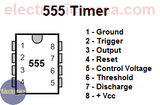
To achieve our goal, a 555 IC timer configured as astable multivibrator is used. With this configuration, a continuous square wave is obtained at the 555 output (pin 3).
- When the output of 555 goes up (+ 12VDC), the electrolytic capacitor C2 is charged through diode D1. The diode D2 is reverse biased and behaves as an open circuit.
- When the output of 555 low (0V), the charge stored in the capacitor C2 is transferred to capacitor C3 through the diode D2 and the 555 IC.
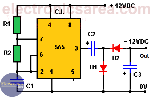
The steps above are continuously repeated. Thus, a -12V DC (negative 12 volts) is always kept at the output. In the charging process of the capacitor C3, the current flow is from the bottom to the top, then the highest voltage is 0V.
List of circuit components for the 12V to -12V DC converter
- 1 2K resistor (R1)
- 1 10K resistor (R2)
- 1 nF capacitor (C1)
- 2 470uF electrolytic capacitors (C2, C3)
- 2 1N4001 diodes (D1, D2)
- 1 555 timer IC
Note: Take note that this 12V to -12V DC converter circuit can get -12V DC, but with little current capacity.
")
")

