Home / Circuits / LED Circuits /
Two-way traffic light Circuit using 555 and CD4017
This Two-way traffic light circuit using 555 and CD4017 achieves the functionality of a typical two-way traffic light using two integrated circuits: a timer and a decade counter. All lights are implemented with 3 high intensity LEDs in series to be more noticeable in the day.
How the Two-way traffic light circuit works?
The CD4017 decade counter integrated circuit has 10 outputs (0 to 9) which are activated sequentially (high level).
The speed of this sequence is given by the 555 timer output (clock). The 555 timer CI is working as an astable multivibrator, and uses a potentiometer to change the duty cycle from 2.5 seconds to 90 seconds.
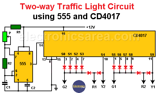
The diagram above shows the connection of circuit components. The sequence of lights is in the following table.
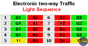
From the table we see that:
- The time that the green light is on is 4 clock cycles
- The time that the red light is on is 5 clock cycles and
- The time that the yellow light is on is 1 cycle.
The red light is on, one more cycle, than the green light. This is because, when the light changes from red to green, this is done without going through the yellow light. When the light changes from green to red, the yellow light is always displayed.
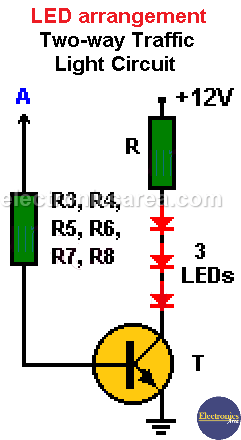
Analyzing the chart we can see the light sequence as CD4017 outputs are activated. These outputs can be applied to various LEDs in series using a transistor as shown in then following image. To handle greater loads, we can use relays.
- Route # 1: G1 = green, R1 = Red, Y1 = Yellow
- Route # 2: G2 = green, R2 = Red, Y2 = Yellow
Six similar circuit could be connected to the G1, G2, R1, R2, Y1 and Y2 outputs.
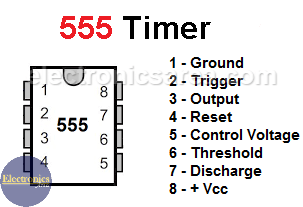
555 IC diagram and pin-out description
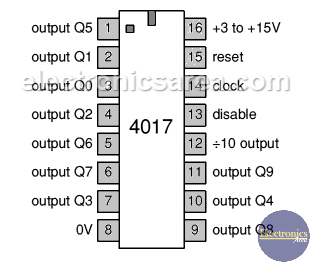
CD4017 IC diagram and pin-out description
- Pins 1 to 7 and pin 9 and pin 11 are outputs for the counter.
- Pin 8 is connected to the negative power supply.
- Pin 12 is the carry-out pin.
- Pin 13 is the “enable” pin.
- Pin 14 is the input clock pin. This is connected to the output of the astable 555 timer.
- Pin 15 is the reset pin. This pin returns the counter to zero.
- Pin 16 is the positive power supply pin.
List of circuit components
- 18 high efficiency white LEDs
- 12 1N914 diodes.
- 6 2N2222 transistors (T).
- 1 10 uF capacitor (C2).
- 1 100uF, 16 volts electrolytic capacitor (C1)
- 1 100K Potentiometer (P).
- 1 4.7 K resistor (R1).
- 1 1.5 K resistor (R2).
- 6 560 ohms resistors (R3, R4, R5, R6, R7, R8).
- 6 100 ohms resistors (R)
- 1 555 timer.
- 1 CD4017 decade counter.
Note: As LEDs are white, a transparent material of red, yellow or green is used to simulate the colors of a traffic light.


