Home / Circuits / Power Supply /
Transistor – Zener Voltage regulator
The Transistor – Zener Voltage regulator is a very simple circuit that uses a zener diode as the reference voltage and a transistor as the current amplifier as its main components. Due to its simplicity, it is very easy to do.
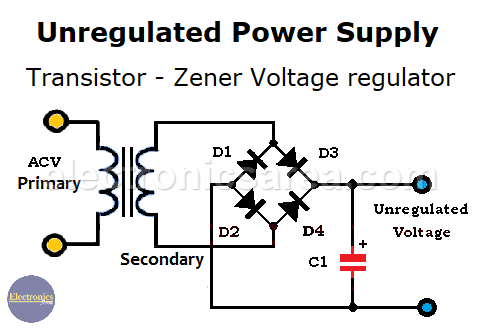
The unregulated power supply
If we use a half-wave rectifier or full-wave rectifier, we convert an alternating current voltage (ACV) into a direct current voltage (DCV). The following diagram shows a typical unregulated power supply.
The output voltage of the rectifier is an unregulated voltage because its amplitude is not constant. The output voltage of an unregulated power source, may change due to load variations (variations of the load current).
To reduce these voltage changes, we can connect a regulator circuit in series with the unregulated power supply. Such a circuit reduces the ripple voltage at the output of unregulated voltage sources and maintains the regulated voltage at a constant value, even when the load varies with time.
Transistor – Zener Voltage regulator
This circuit delivers an output voltage established by the voltage of the zener diode – 0.7 volts. The 0.7 volts is the average voltage drop between the base and the emitter of a transistor. (Vbe). So, Vout = Vz – Vbe = Vz – 0.7 V.
- When the unregulated voltage goes up, the zener diode current will also go up. The voltage across the zener diode has no variation or very little variation, so that the output voltage of the voltage regulator is stable.
- When the unregulated voltage goes down, the zener diode current will also go down. The voltage across the zener diode has no variation or very little variation, so that the output voltage of the voltage regulator is stable.
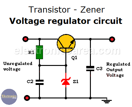
The regulated output voltage will do not change if RL (the load) changes. Changes in the load current is not a problem, since it pass through the transistor.
You may also like the 9 volts power supply using zener and transistor diagram
Transistor – Zener Voltage regulator circuit Components list
- 1 NPN transistor: 2SC1061 (Q1)
- 1 12V or 13V / 1W Zener diode (Z1). A 12V zener diode for an 11.3V output voltage and 13V zener diode for a 12.3V output voltage.
- 1 electrolytic capacitor 470uF (C1)
- 2 electrolytic capacitors 100uF (C2, C3)
- 4 rectifier diodes 1N4002 (D1, D2, D3, D4)
- 1 560 ohms resistor (R1)
- 1 12 VAC, 500mA transformer is connected to the input of the unregulated power supply.