What is a Step Response of an RL Circuits?
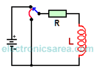
When a constant voltage is suddenly applied to an RL circuit, an increasing a current goes through the conductor and creates a magnetic field that expands with the increasing current. This current will reach a maximum value, and the magnetic field stop expanding.
The expanding magnetic field induces a Counter-Electromotive Force (CEMF) of reverse polarity that opposes the applied voltage (blue line in second diagram).
The value of the CEMF is proportional to the rate of change (derivative) of the inductor current. The faster the change, the greater the electric current. This tries to prevent the increase of the expansion ratio of the magnetic field.
When the magnetic field stops expanding, reaches its steady state, the inductor appears as a resistive load. The resistor, shown in the first diagram, can be interpreted as their internal resistance or an external resistor in series with the inductor. If now the applied voltage is removed, (voltage becomes zero volt (0 V)).
At this time the magnetic field, which was in stable condition, collapses and induces an EMF in the inductor. The inductor tries to maintain the current flow it had before, and thus try to avoid the collapse of the magnetic field.
While this happens, an CEMF tries to prevent the collapse of that magnetic field. This CEMF is generated by the magnetic field current that is collapsing.
To create the magnetic field in the inductor, the source must have done work, for which it needs power. The power delivered by the source is equal to the multiplication of the current delivered by the source and the voltage that flows through it.
This power is transferred to the circuit. The power in the circuit is obtained, multiplied the current by the voltage created by the inductor (which opposes the supply voltage) while the magnetic field increases.
When the magnetic field becomes constant, the voltage across the inductor (induced voltage) disappears because all the energy is already stored.
The voltage induced in the inductor opposes the applied voltage (source voltage), preventing the current increases rapidly when the circuit is closed. (The unit step is applied). (See chart above as current increases). The amplitude of the induced voltage is proportional to the rate of change of current. (blue lines in the second diagram)