Home / Circuits / LED Circuits /
How to make a Police Style Strobe Light Circuit?
This Police Style Strobe Light Circuit uses a 555 timer and a 4017 decade counter ICs to show the familiar lights used on police cars. To achieve this Police Style Strobe Light effect, two groups of LEDs are used. Each group has three LEDs that alternately turn on and off.
Each time a group is activated, its LEDs flash on and off three times. The LEDs can be red for one group and blue for the other.
How does the Police Style Strobe Light work?
This police-style strobe light circuit uses the 555 timer as the clock for the 4017B decade counter. You can change the speed of the clock by changing the resistor and capacitor values connected to the timer. Although the values of the components already chosen work quite well.
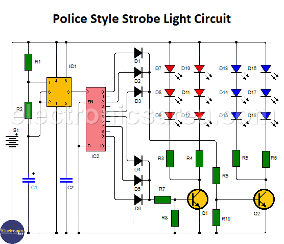
The 4017B provides a sequential high logic level at its outputs. The schematic shows that outputs 0, 2, 4 and 5, 7, 9 are connected to transistors Q2 and Q1 and outputs 1, 3, 6 and 8 are not connected.
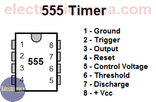
555 Timer IC Pinout
When the 4017 IC activates one of its unconnected outputs, no LED lights and some time elapses. This time is necessary to make the LEDs look like they are OFF. This creates the effect of flashing LEDs (the strobe effect) when each group of LEDs is enabled.
Blue LEDs are connected to transistor Q2 and red LEDs are connected to transistor Q1.
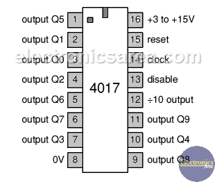
4017 Decade Counter IC Pinout
List of circuit components
- 1 555 Timer (IC1)
- 1 4017B decade counter (IC2)
- 2 2N2222 NPN bipolar transistor or a similar one (Q1, Q2)
- 6 1N4001 diodes (D1, D2, D3, D4, D5, D6)
- 12 red and blue LEDs (D7 to D18)
- 1 1K resistor (R1)
- 1 22K resistor (R2)
- 8 470 Ohm resistors (R3 to R10)
- 1 2.2uF electrolytic capacitor (C1)
- 1 0.01uF capacitor (C2)
The circuit is can be powered by a car battery (B+) or a 12VDC power supply.


