Over temperature alarm circuit using Thermostat
It seems obvious to use a thermostat for this over temperature alarm circuit. We make the clarification because they also can use other devices such as thermistors, diodes, etc. This over temperature alarm circuit can be assembled easily, due to the small number of components required.
How the over temperature alarm circuit works?
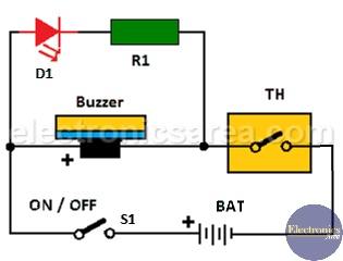
For the over temperature alarm circuit operation, a thermostat is used. This thermostat is activated at a temperature defined by the model itself. The bimetallic thermostat closes and opens its terminals depending on temperature.
When the thermostat terminals are closed, a current flows through it and turns on an LED for a visual warning and a buzzer for an audible warning.
If the sound of a buzzer and the LED light are not enough to attract attention, a relay, with the correct characteristics, can be placed in parallel with the buzzer (between the cathode of the LED and the left terminal of the thermostat). In this way you can also connect a siren or bell to get more attention.
The temperature at which the thermostat is activated depends on the model. For example:
- 67L060 thermostat has an activation temperature of 60° +/- 5°
- 67L090 thermostat has an activation temperature of 90° +/- 5°
Thermostat options are: 67L040, 67L045, 67L050, 67L055 67L110 and so on.
Very important: place the thermostat as close as possible to the place where you want to sense the temperature.
List of components for the over temperature alarm circuit
- 1 1K resistor (R1)
- 1 red LED (D1)
- 1 buzzer (12V)
- 1 12V or 9V battery (BAT)
- 1 thermostat (TH): 67L080
Other temperature alarms you may like:
- Over-temperature alarm using op amp
- Car Temperature Alarm using 741 & 555 ICs
- Temperature alarm circuit with Op. Amp.
- Temperature Alarm u with thermostats


")