Building a NAND gate with transistors and diodes
This NAND gate with transistors circuit, built with transistors, simulates the operation of a NAND gate with two or more inputs. (There is one diode for each input. D1, D2, D3, …, Dn)
How does the NAND gate circuit work?
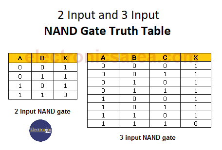
The truth table below shows how the NAND gate works. We can see that the output is a logic “low” when all inputs are in a logic “high” state.
Any other combination of inputs (“Low”, “High”) will cause the output to have a “High” logic level. The figure shows that the circuit uses two transistors operating in the cutoff and saturation regions.
When both inputs are at “high” logic level, the two diodes are inversely polarized and act as an open circuit. Transistor Q1 is biased by resistor R1 and enters saturation.
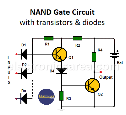 NAND Gate with Transistors & Diodes
The saturation current of the Q1 transistor biases the Q2 transistor, causing the Q2 transistor to go into saturation, resulting in a “low” logic level at the output (the collector of the Q2 transistor).
If any or all of the inputs are logic “low,” the base of the transistor does not have enough voltage to be polarized and transistor Q1 does not conduct. Without the collector current of Q1, transistor Q2 is not biased, there is no current conduction, and the output is a logic “high” level.
Note: The circuit is powered from a 5 volt source.
List of circuit components
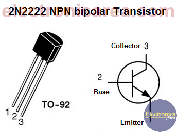
- 2 2N2222 NPN bipolar transistors or equivalent (Q1, Q2)
- “n” semiconductor diodes 1N914 or equivalent (D1, D2, D3, …. Dn)
- 1 2.2 K resistor (R1)
- 1 470 ohms resistor (R2)
- 1 47 K resistor (R3)
- 1 2.7 K resistor (R4)