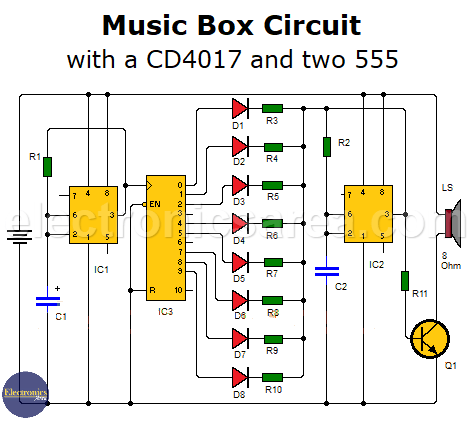
Music Box Circuit using a CD4017 decade counter and two 555
This music box circuit attempts to emulate the operation of a common music box. The maximum number of notes is 10, which allows us to create a simple melody. The circuit uses two well-known integrated circuits: the 555 timer and the CD4017 decade counter.
How does the music box circuit work?
The first 555 is used as the clock for the 4017 decade counter. The operating frequency of the clock can be varied by changing the resistor R1 with a 50K or larger potentiometer in series with a 1K resistor.
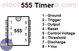
The 1K resistor is needed to prevent a short circuit between the output of the 555 (pin 3) and pins 6 and 2 when the potentiometer has a value of 0 ohms and the 555 timer has an output voltage other than 0 volts.
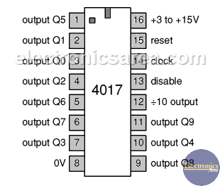
As the operating speed of the first 555 changes, the frequency applied to the clock input of 4017 changes, and consequently the cadence of the music box tones. The output of 555 is connected to the clock input of CD4017. The decade counter provides a high voltage signal on its 10 outputs, starting at output pin “0” and ending at pin “9”.
The diagram shows that outputs 3 and 6 are not used. They are used to create pauses in the melody. Each output of the CD4017 is connected to a diode in series with a resistor. When an output is high, the corresponding resistor is in series with resistor R2 of the second 555. (“R”)
This set of resistors (“R”) and capacitor C2 cause the second 555 to oscillate at a specific frequency. Each time a CD4017 output goes high, the second 555 oscillates at a frequency determined by the group of resistors “R” (resistors connected to the outputs of the 4017), R2, and C2. When the sequence of 10 tones is complete, the process is repeated.
A transistor (Q1) is used to drive the speaker. The transistor goes from the cutoff region to the saturation region according to the oscillation frequency of the second 555.
As you can see, this is a good project to experiment with, and we can get a sequence of notes that we like. You can change the values of the resistors in series with the diodes to experiment with different sounds. You can also change the number and location of the “silences” by leaving the corresponding output pin unconnected and selecting a different output.
The circuit is connected to a 9 VDC voltage source. You can make a simple voltage source with an LM7809 voltage regulator, or you can use a 9 volt battery.
List of Components for the Music Box Circuit
- 2 555 Timer IC (IC1, IC2)
- 1 CD4017 Decade Counter (IC3)
- 1 TIP29 NPN Bipolar Transistor
- 2 33K resistors (R1, R2)
- 3 10K resistors (R3, R5, R9)
- 3 15K resistors (R4, R7, R10)
- 2 22K resistors (R6, R8)
- 1 470 Ohm resistor
- 1 10uF electrolytic capacitor (C1)
- 1 10nF capacitor (C2)
- 8 1N4148 Diodes (D1, D2, D3, D4, D5, D6, D7, D8)
- 1 8 Ohm miniature loudspeaker (LS)


