Multitone generator circuit using CD4001
This multitone generator circuit has many applications, but here it is shown as an open door indicator, generating a different tone for each door of our house, office, etc. For example, you can generate:
– a high tone when the button on the front door of the house is activated.
– a low tone, when the button on the tailgate is activated and …
– a middle tone, when the side door switch is activated.
The diagram shows a multi-tone alarm generator circuit activated with pushbuttons. This circuit has three pushbuttons, each of which produces the generation of its own distinctive tone.
How the Multitone generator circuit works?
The circuit is a simple, monotonous alarm generator system with three inputs. In it, two of the inputs of the CD4001 integrated circuit are connected as an astable multivibrator, and practically does not consume energy when inactive, consuming only a negligible leakage current.
But when a resistor is connected between pins 2 and 5 of the integrated circuit, it is activated and acts as a square wave generator.
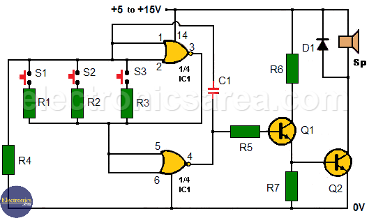
Multitone generator circuit – Open door indicator
Resistors used must have a value lower than the 2.2 mega ohms that have the resistance R4, and the frequency of the tone is inversely proportional to the value of the resistance. With the indicated resistance values, the circuit generates:
- 1500 Hz tone (high tone) approximately when S1 is pressed
- 800 Hz tone (mid-tone) approximately when S2 is pressed
- 450 Hz tone (low tone) approximately when S3 is pressed
Note: You can control more door, adding more switches and resistor.
The generated tones are easily differentiated. The power output of this circuit is about 11 watts. But the final value will depend a lot on the actual impedance values of the speaker and the power voltage being used.
List of circuit components
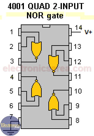
- 1 CD4001 IC (4 NOR 2 input gates) (IC1)
- 1 2N3704 NPN transistor (Q1)
- 1 2N3054 NPN transistor (Q2)
- 1 470K resistor (R1)
- 1 820K resistor (R2)
- 1 1.5M resistor (R3)
- 1 2.2M resistor (R4)
- 1 10K resistor (R5)
- 1 100 ohm resistor (R6)
- 1 1K resistor (R7)
- 1 1000 pF capacitor (C1)
- 1 1N4001 diode (D1)
- 1 5 to 25 ohms speaker
- 3 (or more) NO (normally open) switches (S1, S2, S3)
Note: CD4001 pins 8, 9, 12, 13 are grounded.


