Home / Circuits / DIY Test & measuring /
7-segment display logic probe for TTL circuits
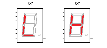
This logic probe with 7 segment display is designed with TTL technology and does not use LEDs to display the high and low logic levels found in many of the logical probes on the market. The circuit shows the capital letter “H” when there is a logical “1” or the capital letter “L” when there is a logical “0”.
This circuit also detects when there is an open circuit because the display has all the segments turned off, indicating that the test point is disconnected.
The logic probe is designed with TTL technology and only serves to diagnose circuits of the same technology.
How does the logic probe with 7 segment display work?
The circuit uses the 7447 7-segment display decoder.
- When, at the input of the logic probe, we have a logical “1”, a ‘1’ is applied to the input C or 4 of the integrated circuit.
- When at the input of the logic tip we have a logical “0”, a ‘1’ is applied to the inputs A, B and D or 1, 2 and 8 of the integrated circuit.
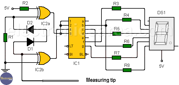
Logic Probe with 7 Segment Display for TTL circuits
If we connect the 7447 decoder in the common way to the 7 segments display, we can see that it does not display the expected letters (H or L). This is because the connections from the output of the integrated circuit to the inputs of the display must be wired in a special way to obtain the letter “H” for the high logic level and the letter “L” for the low logic level.
When there is an open circuit at the input of the logic probe, the four inputs of the decoder 7447 are at logical “high”. Then A = B = C = D = 1 and the display is disabled.
The logic probe with 7 Segment display input consists of two exclusive OR logic gates (IC2b and IC2a) and operates as follows:
– When a logical “low” is applied to the probe, both inputs of the IC2b gate are “low”, so the output will also be a logical “low”.
One of the IC2a gate inputs is held “low” through the resistor R1 and the other is held “high” through the resistor at R2, so its IC2a output will be “high”. The output of IC2a is connected to inputs A, B and D of the 7447.
– When at the input of the logic probe we have a “high”, an IC2b input is “low” and the other is “high”, so the output of the IC2b gate will be “high”. This output connects to the C input of the 7447 IC. Both IC2a inputs are “high”, then the output will be “low”.
– When there is an open circuit in the probe, the inputs of the gate IC2b are not grounded but ‘float’ just below the minimum level of logic state ‘1’. Then the output is a “1”.
When an open circuit is detected, the measured signal reaches one of the IC2a gate inputs, but successive voltage drops across the diodes D1 and D2 cause this voltage signal to decrease, thereby preventing the input to the gate. Gate IC2a switch to “high” and keeping the input “low” through R1. The other input is kept at “1” so that the output equals a logical “1”.
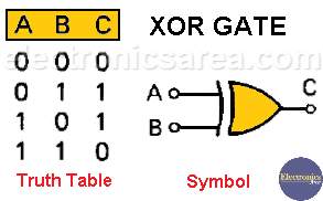
The connections of the encoder 7447 outputs to the 7 segment display inputs are shown in the above diagram. The symbol and truth table of the exclusive OR gate (or exclusive) is shown below.
Circuit list of components
- 1 7447 IC, 7 segment displays decoder (IC1)
- 1 7 segments display, common anode. Litronix DL707 or similar (DS1)
- 1 7486 IC, 4 2 inputs XOR gates (IC2)
- 6 220 ohms resistors (R3, R4, R5, R6, R7, R8)
- 2 470 ohm resistor (R1, R2)
- 2 1N4148 diodes (D1, D2)
This article is based on the Hi Low logic tester article from Elektor Magazine.
More logic probe circuits:
- Logic probe with two transistors
- Logic probe with inverters and diode
- Audible logic probe with 555
- How to Make a Logic probe with NOR Gates (PCB)