Lie detector circuit using two transistors
This simple lie detector circuit consists of two transistors and other additional passive components. The circuit can detect if a person is not telling the truth (the person is lying), using two sensors placed directly on the skin.
How the lie detector circuit works?
To achieve its goal, the lie detector circuit senses the change in the skin resistance. The skin resistance changes when a person lies. This usually occurs by the change in skin temperature, sweat, or other reason. But it happens when the person is lying.
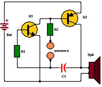
The circuit is a simple two transistor oscillator, whose oscillation frequency depends on the values of capacitor C1, resistor R2 and the skin resistance between the two sensor terminals. The values of capacitors C1 and R2 are fixed, but the skin resistance can vary, and this is what will cause a variation in the sound coming from the speaker. (when a lie is detected).
For the circuit to oscillate, part of the output signal is taken from the Q2 transistor collector, and it is feed back to the input at the Q1 transistor base through capacitor C1. See the circuit diagram.
List of components for the Lie detector circuit
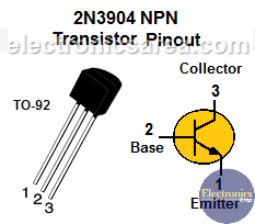
- 1 NPN bipolar transistor, 2N3904 or similar (Q1)
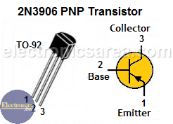
- 1 PNP bipolar transistor, 2N3906 or similar (Q2)
- 1 4.7K resistor (R1)
- 1 82K resistor (R2)
- 1 0.01uF capacitor (C1).
- 1 8 ohms speaker
- 1 9 volt battery. This makes this circuit, a portable device.
Note: The sensors can be two small metal plates that are placed directly on the skin.