Home / Circuits / LED Circuits /
LED Sequencer using 4017 Decade Counter
This LED Sequencer using 4017 decade counter circuit is very easy to build, and shows a sequence of lights (LEDs) that lights up one by one.
How the LED Sequencer using 4017 works?
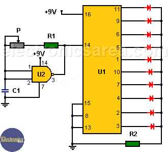
The first part of the circuit (left side) is an oscillator that delivers at its output a square wave. The frequency of the output wave depends on the values of the capacitor C1, the resistor R1 and potentiometer P. The oscillator frequency is changed by turning the knob of the potentiometer.
LED Chaser / LED Sequencer using 4017 Decade Counter
The square wave is applied to the clock input of CD4017 decade counter. Ten LEDs are connected to the 4017 decade counter outputs. LEDs light up in sequence. (only one LED is on at a time).
On this case, a single LED lights, while the others are off. To achieve a “sequential off” (all LEDs are turned On and only one is Off), the connection of LEDs is reversed, we remove the 1K resistor (see R2 at the bottom of the diagram) and, we place a 1K resistor in series with each LED.
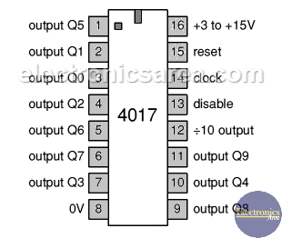
4017 Decade Counter pin out
You can obtain bigger frequency variations for the 4017 clock, replacing the current capacitor (C1), with one of a different value and adjusting the potentiometer (P).
List of components for the LED Sequencer circuit
- 1 100K resistor (R1)
- 1 1K resistor (R2)
- 1 1M potentiometer (P)
- 1 4.7 uF (microfarad) capacitor (C1)
- 10 LEDs
- 1 4017 decade counter (U1)
- 1 CD4011 (four 2-input NAND gates) (U2)
Note: The circuit can be powered by a 9 volt power source or a battery of the same voltage.


