Inductor in DC and AC
The inductor and the direct current (DC)
An inductor is made from a conductive wire, forming something similar to a spring coil. If a DC current (current that does not vary over time) is applied to an inductor, it behaves like a short circuit. The current will pass through the inductor with no opposition.
But in the inductor if there is opposition to the current flow. This happens when the connection to the voltage source is made and lasts a very short time (transient state). What happens in that small space of time is that the current is varying from 0V to its final value DC.
The inductor and the alternating current (AC)
The inductor, such as resistance, opposes the AC current flow, but unlike the latter, the value of this opposition is called inductive reactance and is represented by XL and can be calculated with the Ohm’s law: L = V/I and by the formula: XL = 2πfL, where:
- – XL: inductive reactance in ohms
- – V: voltage in volts
- – I: current in amps
- – π: constant (pi): 3.1416
- – f: frequency in hertz
- – L: inductance in Henry
See: Common units Definitions in Electronics
Phase angle of the alternating current in an inductor
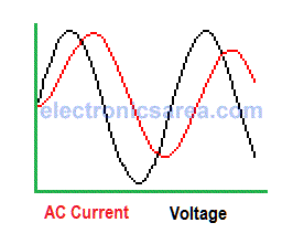
The voltage. Electrical Potential difference in an inductor leads the current by 90°. AC signals have the characteristic of being periodic, this means that it is repeated at fixed intervals of time.
- If two equal periodic signals are in phase, maximum and minimum values match.
- If a signal is delayed relative to another, until they return to match these (maximum and minimum) values, it is said to have a phase shift of 360°.
Intermediate gaps would be 180° (waves are offset half a period) and phase shift of 90° (waves are offset a quarter of the period).
The quality factor (Q) of an inductor
For the inductive reactance (XL) previously calculated, we have taken the inductor as ideal. A real inductor has an associated resistance RL due to material that is made, and if the inductor has a core that is not air. This resistance (RL) is placed in series with the inductor.
The relationship between the inductive reactance XL and resistance RL is called “Quality Factor”. Q = XL/RL, where RL is the series resistance. Xl and RL are frequency dependent, so Q is also frequency dependent. Less RL means higher Quality Factor.
Note: The Quality Factor is only used for the case of an inductor on alternating current.


