What is a Combinational circuit?
A combinational circuit is, as its name suggests, a circuit where the output depends only on the “combination” of the inputs at the time we are testing the output. Analyzing the circuit made of digital gates shown below, the output of each depends only on their inputs.
The output F will change if the input A or input B or both at the same time change. Combinational logic circuits are made of basic gates: AND gate, OR gate, NOT gate.
They can also be built with NAND gates, NOR gates, XOR gates, which are a combination of the three basic gates. To understand a combinational logic circuit, we can write its Boolean equations and its truth table.
Combinational circuit example
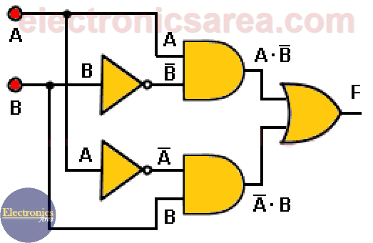
The Boolean equation of the above circuit is:
![]()
The truth table of the circuit above is:
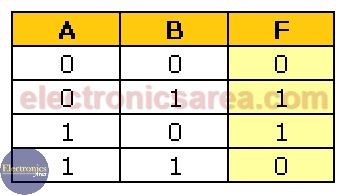
You can see from the truth table that the last column “Output F” only depends on the current A and B inputs.
This diagram and its respective truth table are a specific example. Other diagrams can have more inputs (A, B, C, … etc.), more outputs (F1, F2, F3, …, etc.) and you would have to obtain the truth table for each output depending on the existing inputs.
Note: The outputs in any other combinational circuits can be anywhere in the circuit diagram.