Blown Fuse Indicator Circuit using one transistor
This blown fuse indicator circuit warns us, by lighting a LED, when there is a problem in an electrical installation protected by the fuse.
It is very important to correct faults in the electrical system of a car or motorcycle or another, as soon as possible.
If you don’t know that a fuse is blown, you may run into trouble when the problem is harder to solve. For example, at night or far from a mechanical workshop.
How the blown fuse indicator circuit works?
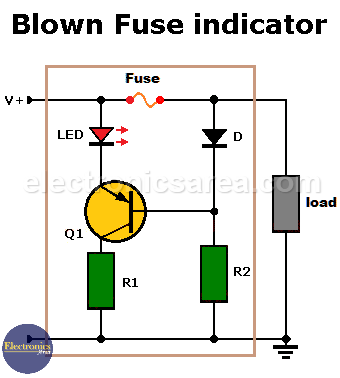
The circuit shown in the diagram is made up of few elements. The most important is a PNP bipolar transistor, which functions as a switch.
Blown Fuse Indicator Circuit using one transistor
– If V+ is present and the fuse is good, the transistor will be in the cutoff region and will not conduct. (see that the voltage at the base of the transistor is V + – 0.7 volts) and consequently the LED does not light up.
– When the fuse blows, no current flows through it and the voltage level at the base of the transistor drops to zero volts. The transistor enters the saturation region (there is an electric current flowing through the emitter and collector), the LED lights up warning that there is a problem.
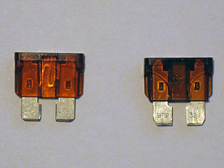
Car_fuses intact and broken
Cqdx, CC BY-SA 3.0, via Wikimedia Commons
There are many fuses in a car’s electrical system. To have a general control of all fuses, you can put this circuit in parallel with each fuse. This circuit can also be used in toys, car radios, and almost any DC or battery circuit.
Blown Fuse Indicator Circuit Component List
- 1 BC558 or NTE159 PNP bipolar transistor (Q1)
- 1 1N4001 or 1N4148 semiconductor diode (D1)
- 1 red LED
- 1 510 ohm resistor (R1)
- 1 510 K resistor (R2)
Notes:
- The circuit is powered from the same DC source, the load use.
- It is always advisable to carry spare fuses of each type that the car or motorcycle needs

")

