8 LED VU meter circuit using LM324 IC
This 8 LED VU meter circuit can be used to display the variation of an audio signal in a group of 8 LEDs, behaving like a VU meter. We could use a specific integrated circuit used for VU meters, but we decided to use a readily available integrated circuit: The LM324 operational amplifier.
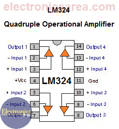
Each of the integrated circuits has 4 operational amplifiers. As we need eight of them, two integrated circuits are used. The 8 op amps are used as voltage comparators. See the diagram.
How the 8 LED VU meter using LM324 IC work?
The output signal of an audio amplifier (which is connected to the input to the speaker), is applied to all the inverting inputs of the operational amplifiers, through resistor R1. R1 and R9 form a voltage divider to reduce the amplitude of the input signal.
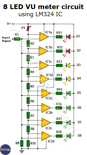
This signal will vary according to changes of music and make the LEDs light, according to the voltage level of the audio signal. The non-inverting pin of operational amplifiers are connected to a voltage divider network, composed of several resistors in series.
This means that the non-inverting terminals of the operational amplifier have predetermined fixed voltages. Whenever the input signal into an operational (in the inverter pin) exceeds the voltage corresponding non-inverting pin, the output is set low, lighting the LED. See the diagram.
Notes:
- V+ = 12V.
- The normal behavior of a VU meter is logarithmic. The VU meter presented here is linear.
- The P1 potentiometer is used to adjust the level of activation of the LEDs.
You may be interested in the 6 LED VU meter using one transistor circuit or an audio level indicator circuit.
List of components for the 8 LED VU meter
- 2 LM324 operational amplifier (IC1, IC2)
- 2 red LEDs (D1, D2)
- 2 yellow LEDs (D3, D4)
- 4 green LEDs (D5, D6, D7, D8)
- 8 1K, 1/4 Watt resistors (R1, R2, R3, R4, R5, R6, R7, R8)
- 2 20K, 1/4 Watt resistors (R9, R10)
- 7 330 ohms, 1/4 Watt resistors (R11, R12, R13, R14, R15, R16, R17, R18)
- 1 50K potentiometer (P1)

")

")