Home / Circuits / Power Supply /
12V to 9V DC Converter
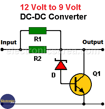
This 12V to 9V DC converter is very useful to power 9V DC devices in a car that uses a 12V battery. The maximum current consumption allowed by this circuit is 0.8 amps. This 12V to 9V DC converter is implemented using a zener diode and a NPN bipolar transistor (Q1) as shown in the circuit diagram.
To better understand the operation of this circuit, the following article is recommended: Zener voltage regulator.
How the 12V to 9V DC Converter works?
As in the zener voltage regulator from the above suggested link, a series resistor is used (R1 and R2 are used in parallel in this case).
The output voltage of the circuit is the zener diode voltage plus the transistor base – emitter voltage. (Vout = Vz + Vbe). Vout = 8.2 + 0.7 = 8.9 volts. A greater variation of the output current is allowed using the NPN transistor. This is not the case when the zener diode is used alone.
Notes:
- Use a heatsink as large as possible for the Q1 transistor.
- The converter input voltage must not exceed 14 Volts.
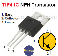
TIP41C NPN Bipolar Transistor Pinout
List of components for the 12V to 9V DC converter
- 1 TIP41C NPN bipolar transistor or similar (Q1).
- 2 6.8 ohm resistors (5 watts or more) (R1, R2).
- 1 1N756 zener diode 8.2 volts or similar (D).
- 1 heatsink to be used on the Q1 transistor (required).
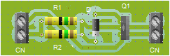
Suggested printed circuit board (PCB)
The following diagrams show a suggested printed circuit board (PCB) and an approximate view of the final circuit appearance.

You may also like the 12 volts to 5 volts converter circuit, that uses de lm7805 voltage regulator IC.

")
")
